1
2
3
4
5
6
7

We designed and built a robot to test a planner and controller which directly minimizes the theoretical risk of failure for each step.
For some more detailed information about things that have come out of this project, I’ve attached some of the finished content that has come out of this project.
You can download my undergraduate thesis, which goes into painfully explicit detail on the mathematics behind the risk-gradient planner and controller.
An overview of the project with some more detail
Documentation of Robot’s Mechanical Design Choices
A poster on some experiments that I ran on one of our initial prototypes
And a poster about part of the work I did on the controller development.
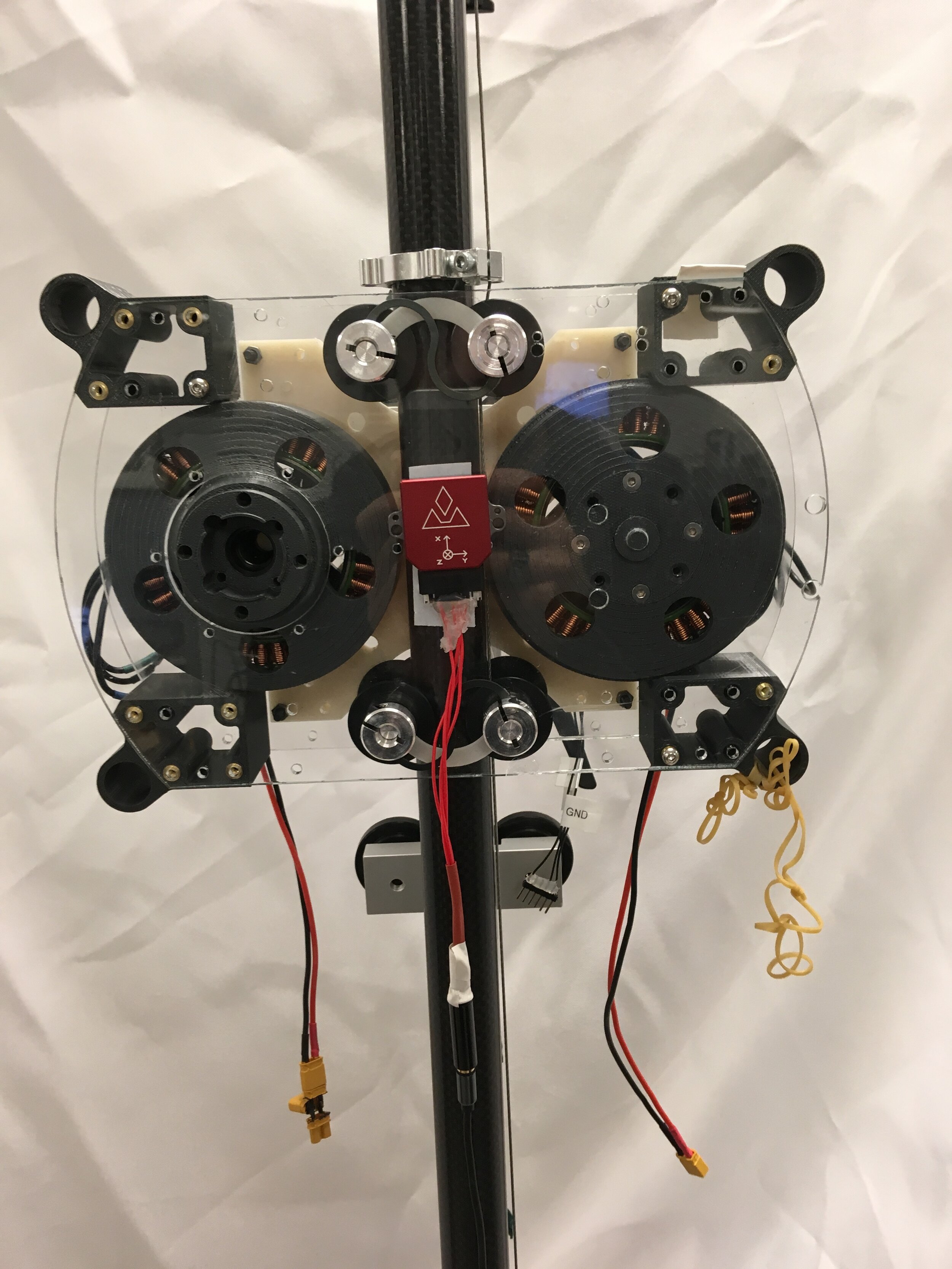
Revision 2 of the pogobot
The clear acrylic plates would not be nearly strong enough for our intended use for it, but gave us a clear window into the internals for debugging. This model was used to test the fidelity of the leg’s force controller, essential for the proper performance of the robot under the risk controller.
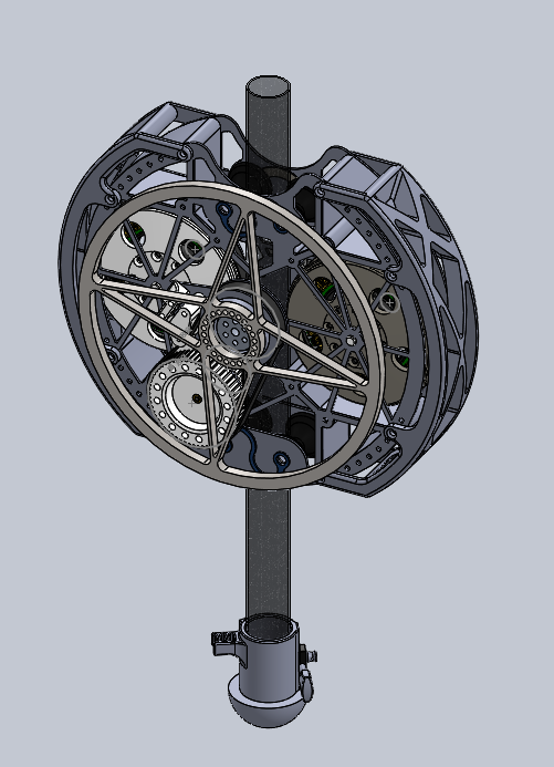
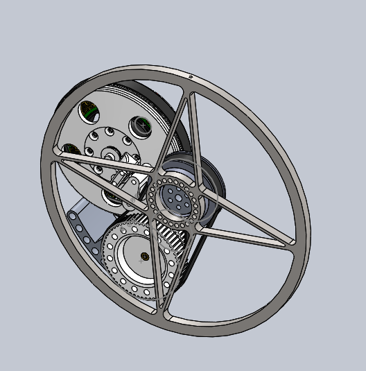
CAD for Revision 3 of the Pogo-bot
The round-body allows for the internal space to add a second stage to the reaction wheel. The 1:3 gear ratio from the reaction wheel motor to the reaction wheel gave us the runtime we need to perform our most aggressive planned actions.
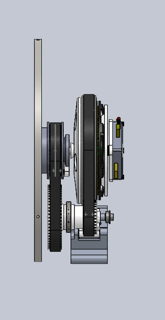
Side view of the reaction wheel drivetrain
Reaction wheel mechanism
Belt drove with a ratio of 1:3 from the motor to the Reaction wheel, this was the most complex mechanism on the robot.
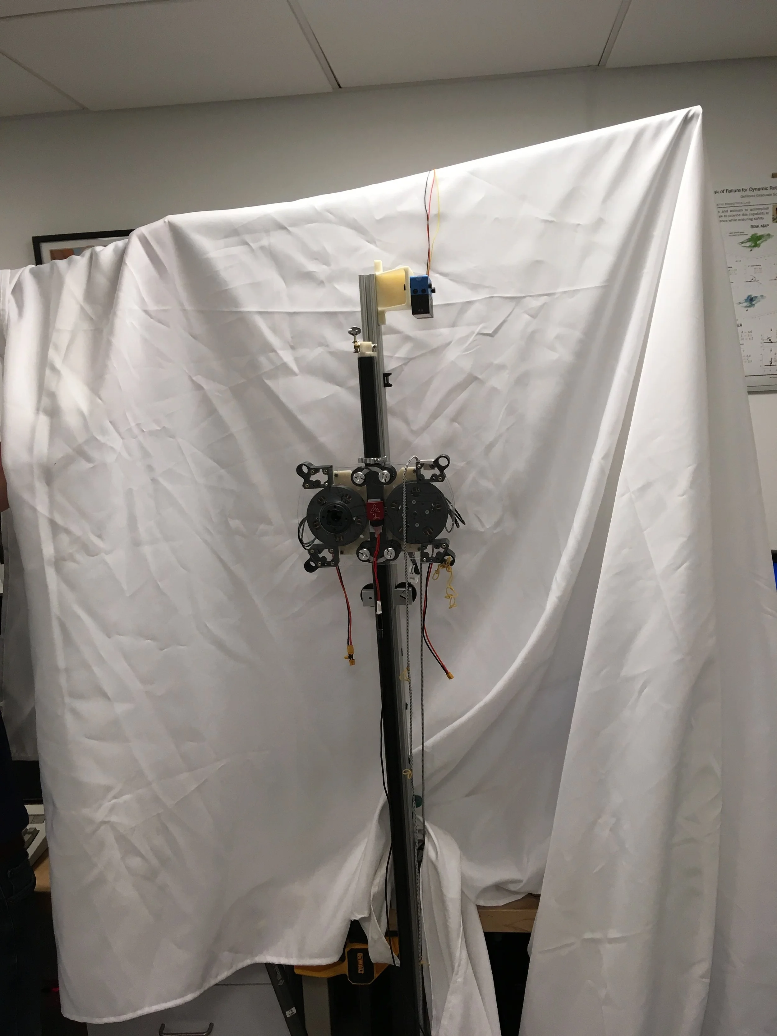
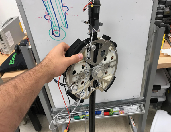
The Assembled Revision 3 body
This time outfitted with steel plates for added rigidity, this version of the pogobot has all of the features internally which we would need for our testing.
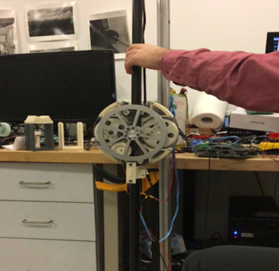
Balance Testing
Unfortunately, the end of my time at MIT came before the robot was ready to be fully tested. We did manage to get the robot to maintain an upright position for 10 seconds or so before the reaction wheel saturated. An offset in the orientation estimate would need to be included to account for the CG not being directly above the leg.