1
2
3
4
5
6
7

Design and Manufacturing (2.007)
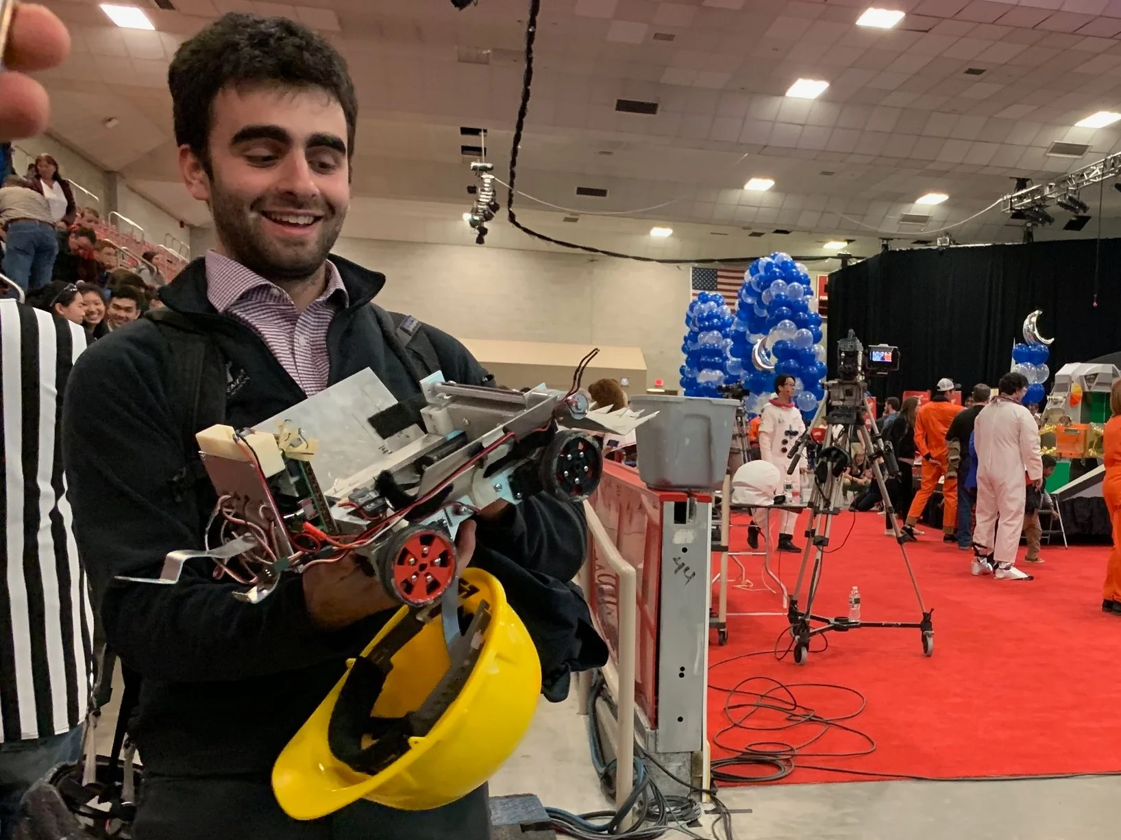
2.007 revolves around a robot competition. Given a kit of materials, including various stock aluminum, electronics, plastics, ect. Each student individually designs and builds their very own robot, which takes on a set of competition tasks laid out at the beginning of the semester. This was a picture of me right after getting knocked out of final competition bracket.
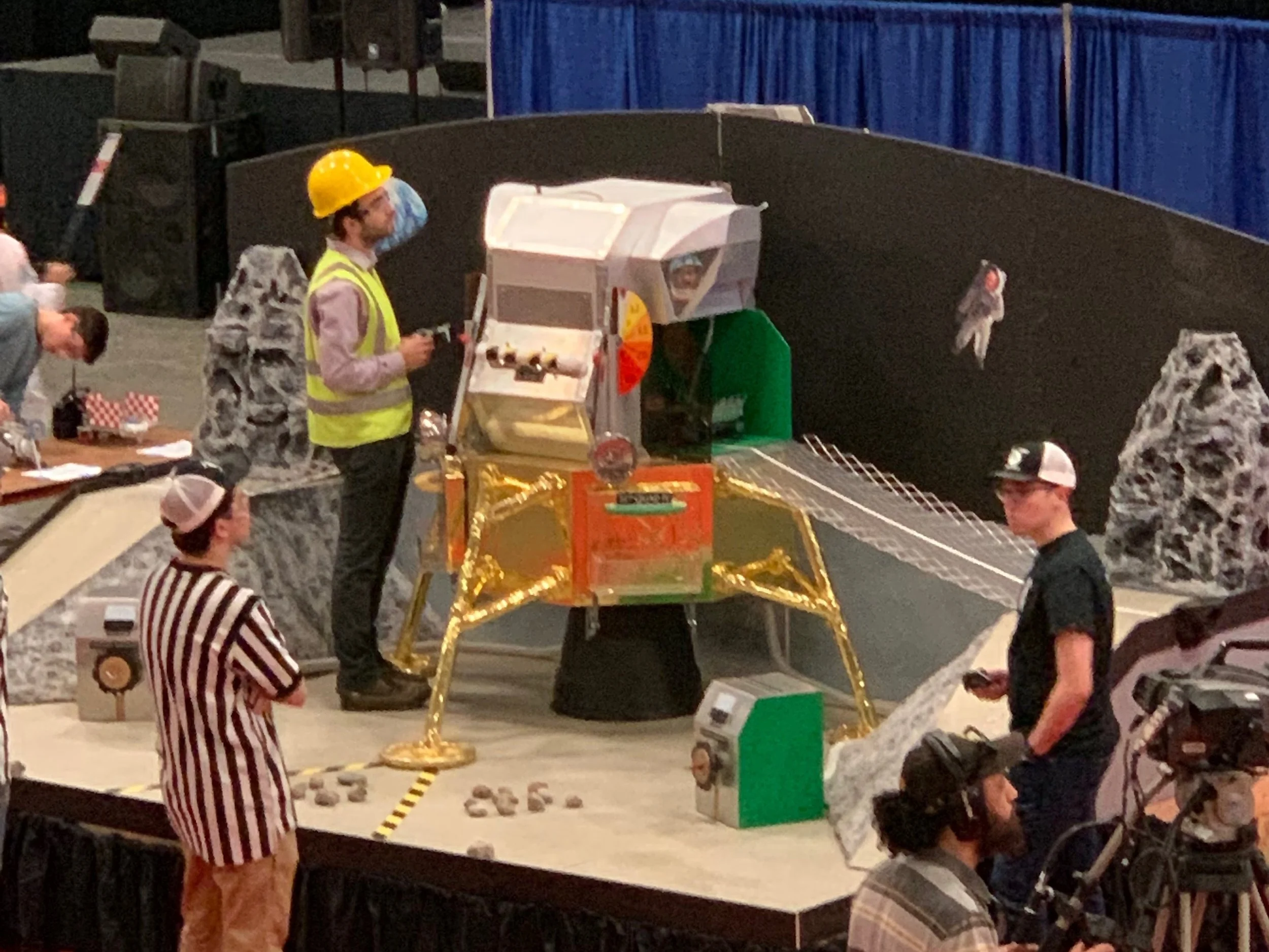
The Competition Board
The robots started on the first level of the lunar lander, drove down two ramps to the floor of the gameboard. Along the way robots had the chance to plant a flag. Once it got down to the floor you could pick up rocks and put them in a number of places. You could also spin the “APS charger” for some number of points, or remove “excess fuel cells” from the outside of the lander. My robot focused primarily of picking up rocks and driving them back to the lunar module.
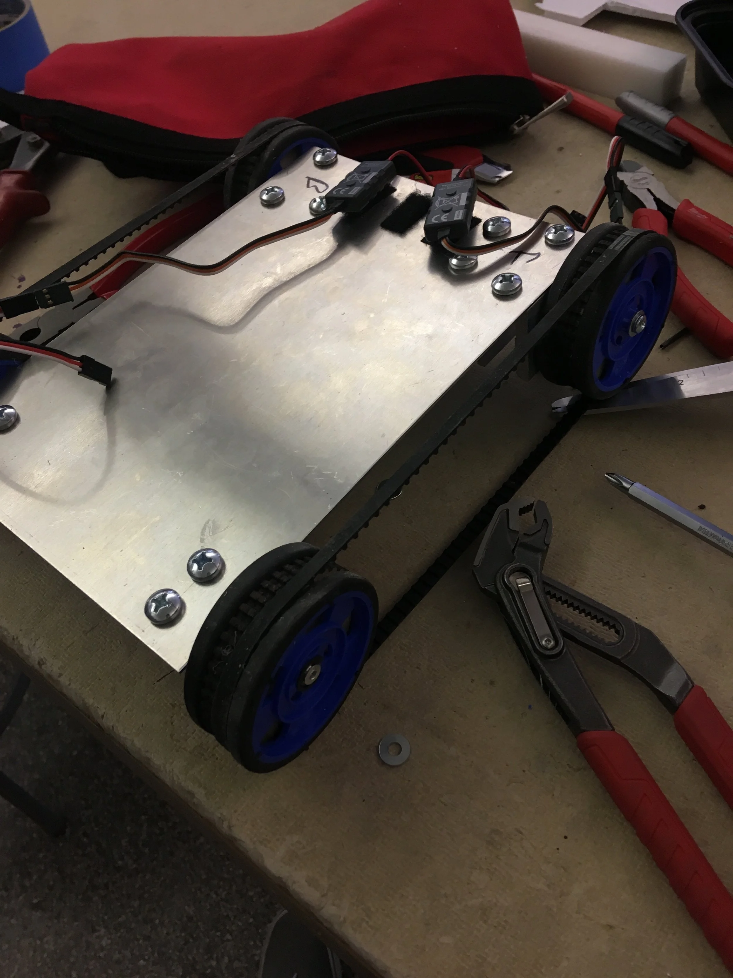
The drivetrain
I spent most of the semester focusing on the design and construction of the drive train of my robot. It wasn’t always suppose to be this way, but proved to be way harder than I initially anticipated, so I sunk most of my time into it. This was iteration one. It worked great, so long as the timing belts didn’t ride themselves off the edges of the wheels. Oh, and it was really tough to assemble…
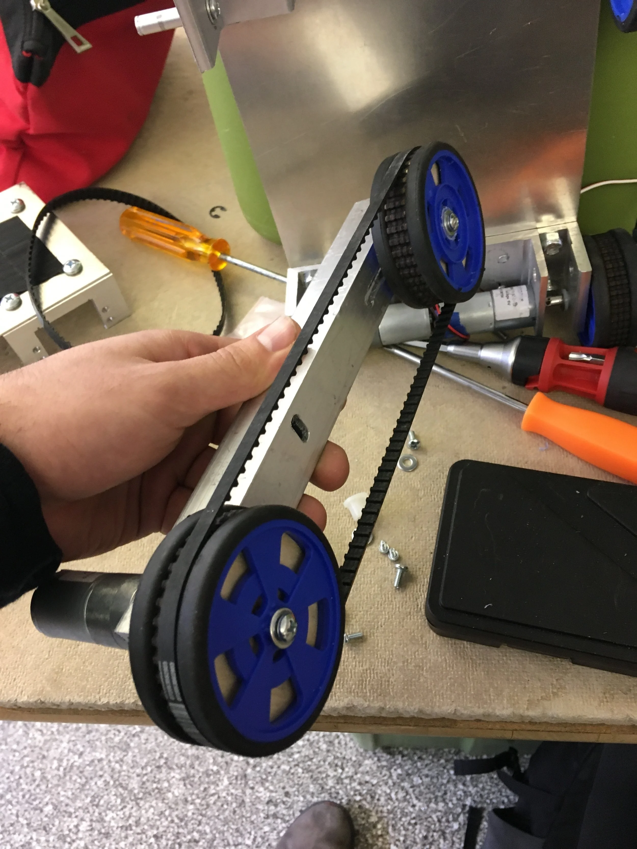
Iteration 2
So I figured that the reason my treads where slipping off was misalignment. In order to get the alignment right, I made each half of the wheelbase for the robot out of a single square bar. I hoped that this would guarantee alignment, and also make the robot easier to assemble and test. The alignment was fantastic, the assembly was straightforward, but the wheels still slipped off… Back to the drawing board.
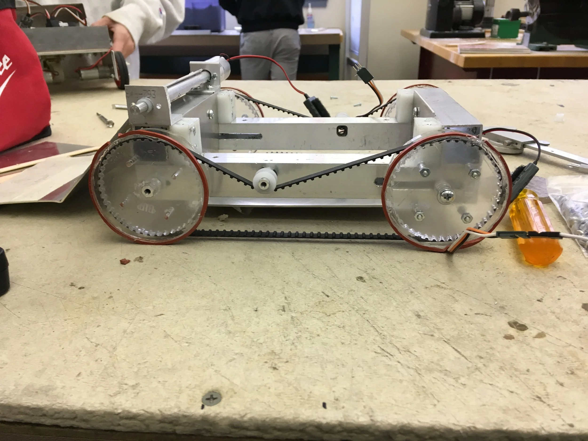
Final iteration
As it turned out, misalignment was not the trouble. Instead, the problem was with my timing pulleys: I had laser cut each one out of a single piece of 3/4 inch plywood, which meant that the whole toothed surface was tapered. As the timing belt spun, it rode up the very slight slope of the plywood and eventually off the wheel. For this iteration, instead of using a single piece of plywood, I cut each pulley out of two pieces of acrylic, and oriented the taper outward, in order to center the timing belt. I also laser cut my own wheels, which now raised the timing belt off the ground in order to keep it from sliding off as the robot turned.
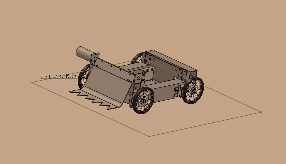
Final CAD model
But alas, the tread design suffered from a great deal of unmodeled friction. After tensioning the belt, it was impossible to make it up the hill. So after 2 months of painstaking work on the tread concept I ditched it, it was time for a re-design. In this version, instead of connecting the wheels with a timing belt, I wired both motors on one of the sides in parallel to the motor driver. This robot was slower than my initial design intent, but I decided that predictability was very important, and the high torque motors kept the robot’s speed extremely consistent.
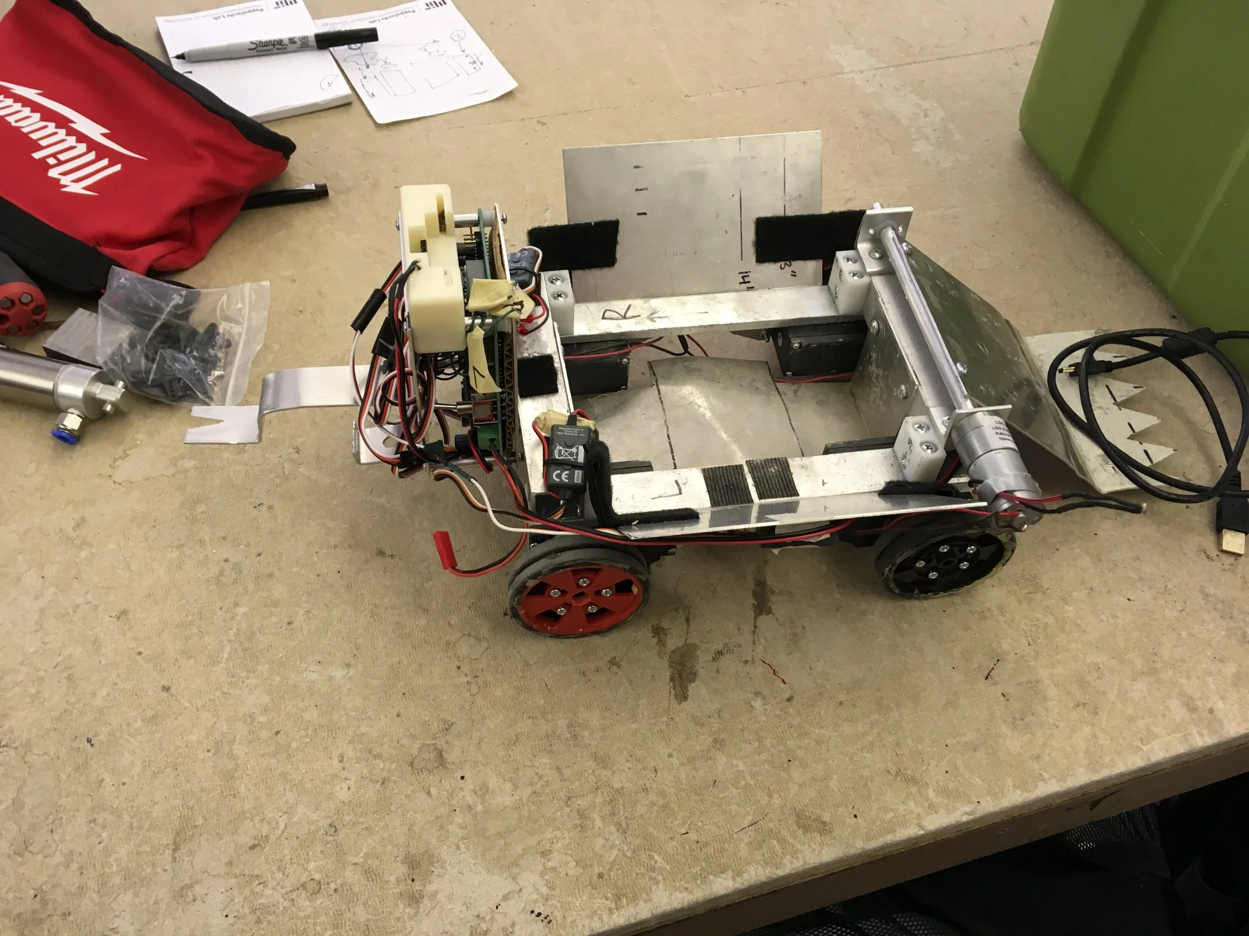
The final robot...
After finishing the CAD model, I got around to building and testing the robot. I had about a week, so I added the block on the left, which housed an arduino controller, the PS2 controller receiver, and a little wedge to carry a flag. I also added those two aluminum wings on the side to stop rocks from falling off the sides as the scooper tossed them in.